|
IRSOL
C++ code implementing socket server for interacting with Baumer camera.
|
|
IRSOL
C++ code implementing socket server for interacting with Baumer camera.
|
This guide lists the steps one should take to configure a Baumer VCXG.2-51M camera.
In particular, it will show how to:
The documentation and SDK access for the Baumer camera is available through the Baumer website. In particular, the following resources are useful:
C and C++ clients) for interacting with the Baumer camera programmatically.C and C++ clients) for interactive with the Baumer camera programmatically.The irsol project developed within this repository is making use of the Baumer neoAPI as an SDK to interact with the physical camera. Documentation for that SDK is available here.
The following diagram is a schematic representation of how one needs to connect the Baumer camera to the host PC. This setup includes:
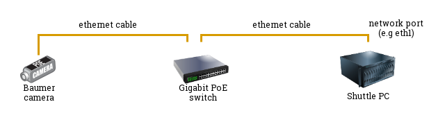
Once the different parts are connected together, you should see that the Baumer camera has a single green light (non-blinking) turned on. If you see a blinking led, the connection is incorrect.
A critical part for allowing the Shuttle PC to connect to the Baumer camera, relies in making sure the two components have "compatible" IP addresses. In particular, the following network configuration is necessary (to be configure only once):
Assuming the network interface of the Shuttle PC against which the ethernet cable is connected is eth1 , you can check the IP configuration of that port via:
In the above example, we understand that the eth1 network port of the Shuttle computer is mapped to the following IP address: 192.168.1.1 with a subnet mask (/24) corresponding to 255.255.255.0.
A utility tool named gevipconfig (distributed with both Baumer GAPI SDK and Baumer neoAPI, but also available for convenience in this repository inside the src/external/neoapi/tools folder) facilitates the configuration of the IP and Subnet for the Baumer camera. A valid IP address has to be in the subnet of the network interface card, the device is connected to and has to be unique.
It is possible to manually set and persist a static IP address to the Baumer camera following these steps:
gevipconfig tool: 192.168.1.1)255.255.255.0)700011810487)192.167.10.12)255.255.0.0)Set the IP address and the Subnet of the Baumer camera to be compatible with the IP address and the Subnet of the Shuttle PC. This can be done via the following command:
Note: the combination of IP and subnet configurations must be a valid combination. The following are examples of correct/incorrect combinations:
invalid: different subnet
NIC: IP 192.168.1.1 Subnet 255.255.255.0 Camera: IP 192.168.2.1 Subnet 255.255.255.0
NIC: IP 192.168.1.1 Subnet 255.255.255.0 Camera: IP 192.168.1.1 Subnet 255.255.255.0 valid: same subnet and different IP address:
NIC: IP 192.168.1.1 Subnet 255.255.255.0 Camera: IP 192.168.1.2 Subnet 255.255.255.0
To follow the valid example above, one could run the following command:
More details are available in the gevipconfig documentation The gevipconfig-tool.
Once the camera and its network configuration has been completed, you can verify the correctness of the setup by running any of the available examples that you can build following the Development Environment Configuration instructions.